Keeping The Lights On: Ensure Your Users and Critical Applications Are Protected With Redundant Cloud Connectivity
- Cloud networking
- April 6, 2020
- RSS Feed
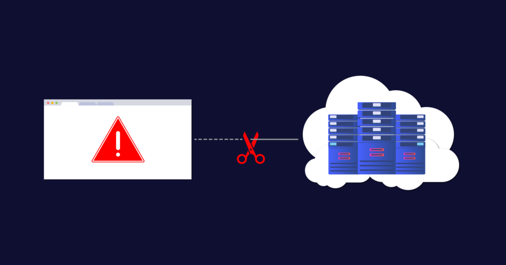
Do you have any single points of failure in your connectivity? Check the design of your network connectivity and protect your critical cloud applications as I run you through some redundancy best practices.
As businesses have continued to shift their workforces to work-from-home and remote operations, our dependence on cloud services continues to grow. Microsoft reported a 775% increase in the use of its cloud services in regions that have recently enforced social distancing.
How we connect to cloud resources plays a critical role in application performance, availability, and usability. It’s now more critical than ever to protect your production and mission-critical applications from disruption through resilient and redundant network architectures. Even the smallest down time can be costly, causing lost productivity, lost revenue, lost data, and in some cases even irreparable impact to brand credibility.
What do the Cloud Service Providers say?
Most Cloud Service Providers (CSPs) expect redundancy and diversity to be handled by the user – for example, AWS say this:
“AWS recommends customers use multiple dynamically routed, rather than statically routed, connections to AWS at multiple AWS Direct Connect locations. This will allow remote connections to fail over automatically. Dynamic routing also enables remote connections to automatically leverage available preferred routes, if applicable, to the on-premises network. Highly resilient connections require redundant hardware, even when connecting from the same physical location. Avoid relying on a single on-premises device connecting to a single AWS Direct Connect device. Avoid relying on AWS Managed VPN as backup for connections that are greater than 1Gbps.”
Google address redundancy and service availability like this:
“For the highest level availability, Google recommends the 99.99% availability configuration. Clients in the on-premises network can reach the IP addresses of VM instances in the selected region through at least one of the redundant paths and vice versa. If one path is unavailable, the other paths can continue to serve traffic.
“99.99% availability requires at least four VLAN attachments across two metros (one in each edge availability domain). You also need four Cloud Routers (two in each GCP region of a VPC network). Associate one Cloud Router with each VLAN attachment. You must also enable global routing for the VPC network.
“For layer 2 connections, four virtual circuits are required, split between two metros.”
So what exactly does protecting connectivity to these applications look like?
Physically redundant network hardware and multiple on-premises data centre locations are the ground floor for protecting your connectivity. Add to that a network provider –or preferably multiple – that can deliver diverse connections into one or more public cloud regions, and then you are protected on both sides of your network connection.
Cost, deployment, or planning limitations sometimes restrict the use of multiple network hardware devices or on-premises infrastructure sites.In these cases it’s still worth considering which components of your overall architecture can be improved upon when designing a solution to minimise single points of failure. This includes whether your backup connections can depend on public internet VPN connections as a means beyond your direct private network connections.
But what if my business was born in the cloud?
The same design principles apply to ‘born in the cloud’ businesses. While on-premises physical connectivity isn’t involved, creating redundant virtual networks and connections between mission critical environments is essential.
As you should expect, redundant best practices are built into the core of the Megaport network: our customer-facing routers have dual uplinks to diverse cores and our transit VXCs Layer 2 access circuits (Virtual Cross-Connect or VXC) are path protected across our backbone.
I think I have redundancy – how can I check?
In my experience, a lot of businesses could be better protected when it comes to their network and cloud applications. To make sure you’re adequately protected, give yourself a quick check up of your redundancy below. I’ve shown some common scenarios and potential pitfalls and run through which components you should consider deploying, based on your existing hardware and device configuration availability.
The scenarios I’ve outlined range from a basic, partially protected network, all the way to end-to-end highly available resilient networks accessing your public cloud environments. So find where your business fits, and make sure your network is redundant, compliant, and highly available.
Redundancy check up: common scenarios and best practice
.panel-title a[aria-expanded=true] svg { transform: rotate(180deg); transition: all 0.3s linear; } .panel-title svg { float: right; padding-top: 5px; }
Single Data Centre and Device:
Only single Customer Premises Equipment (CPE) is available.
- Configure two physical network ports and two private network connections to a diverse cloud on-ramp.
- Configure LAG (link aggregation) to both physical ports on the network device to provide port redundancy in case one of the links fail.1
- Depending whether your public cloud services are hosted in one or more cloud regions:
(a) Configure network connections to diverse cloud on-ramps in a single region
(b) Configure network connections to diverse cloud on-ramps in multiple regions
Prerequisites:
- On-premises CPE supports LX Optical 1Gbps or LR Optical 10Gbps Ports.2
- On-premises CPE supports BGP.

Considerations:
- Single CPE acts as a single failure domain – any device-level failure on the CPE results in a service disruption.
- Multiple physical and logical connections from Megaport to diverse cloud on-ramp locations add fault-tolerance between the CPE and cloud provider.
- Network capacity across both VXCs should be provisioned to ensure a failure of one connection doesn’t result in saturating the redundant VXC.
Single Data Centre and Multiple Devices:
Multiple CPEs are available on the same customer network.
- Configure a minimum of two physical network ports: one for each CPE and one network connection – each to a diverse cloud on-ramp.
Prerequisites:
- On-premises infrastructure has two physically separate CPEs.
- On-premises CPE supports LX Optical 1Gbps or LR Optical 10Gbps Ports.2
- On-premises CPE supports BGP.

Considerations:
- Multiple physical CPEs increase fault tolerance, preventing an individual device failure from resulting in a service disruption.
- Multiple physical and logical connections from Megaport to diverse cloud on-ramp locations add fault-tolerance between the CPE and cloud provider.
- Network capacity across both VXCs should be provisioned to ensure a failure of one connection doesn’t result in saturating the redundant VXC.
Multi Data Centre and Single Device:
Single CPEs are available at separate data centres on the same customer network.
- Configure a minimum of two physical network ports: one for each CPE and a minimum of one network connection – each to diverse cloud on-ramps.
- Depending whether your public cloud services are hosted in one or more cloud regions:
(a) Configure network connections to diverse cloud on-ramps in a single region
(b) Configure network connections to diverse cloud on-ramps in multiple regions
Prerequisites:
- On-premises infrastructure has a CPE at each site.
- On-premises CPE supports LX Optical 1Gbps or LR Optical 10Gbps Ports. 2
- On-premises CPE supports BGP.

Considerations:
- Multiple data centres increases fault tolerance, preventing a data centre failure from resulting in a service disruption. A failure across both data centres would be needed to result in a service disruption.
- Separating the physical and logical connections across diverse data centres, diverse Megaport locations to diverse cloud on-ramp locations further increases fault tolerance and reduces the likelihood for a service disruption.
- Any single failure across the connections out of Site 1 data centre would result in all traffic routing out of Site 2 data centre. In some scenarios this may be undesirable due to stateful firewalls or constraints on network capacity between sites within the customer network.
Multi Data Centre and Dual Devices:
Dual CPEs are available at separate sites on the same customer network.
This level of redundancy would ensure a significantly improved SLA of 99.99% from CSPs like GCP and AWS
- Configure a minimum of two physical network ports per site; one for each CPE and a minimum of one network connection each to a diverse cloud-on ramp.
- Depending whether your public cloud services are hosted in one or more cloud regions:
- (a) Configure network connections to diverse cloud on-ramps in a single region
- (b) Configure network connections to diverse cloud on-ramps in multiple regions
Prerequisites:
- On-premises infrastructure has multiple CPEs at each site.
- On-premises CPE supports LX Optical 1Gbps or LR Optical 10Gbps Ports. 2
- On-premises CPE supports BGP.

Considerations:
- Multiple CPEs at each data centre increases fault tolerance, treating each device, in each site, as its own failure domain.
- Maintaining physical and logical diversity from each Megaport location to multiple, diverse cloud on-ramp locations provides a highly resilient network architecture.
- Multiple failures would need to occur in Site 1 data centre to result in routing convergence and traffic out of Site 2 data centre. This provides a more stable, predictable architecture and works very well with stateful firewalls on the customer network that need to maintain session affinity.
- For additional resiliency, consider using MC-LAG (Multi-chassis Link aggregation) from each CPE to both physical ports on the Megaport switch to provide port redundancy, across diverse CPEs in case one of the links fail.
No Data Centres and Dual Megaport Cloud Router (MCR):
Dual MCRs are used for cloud-to-cloud routing between two different CSPs
- Configure a minimum of two MCRs; one for each routing zone and a minimum of two network connections each to different CSPs.
- The MCRs are active/active:
- Configure MCR1 primary connections to each CSP
- Configure MCR2 with secondary connections to each CSP using diverse cloud on-ramps
- Configure Bi-directional Forward Detection (BFD) on each BGP session between the MCR and CSP, where supported.

Considerations:
- Multiple MCRs in diverse routing zones increases fault tolerance, treating each cloud router as its own failure domain.
- Maintaining logical diversity from each MCR to multiple, diverse cloud on-ramp locations provides a highly resilient network architecture.
- The MCRs do not share routes, this allows them to operate as two ships in-the-night, providing load balancing between each CSP.
- The MCR supports BFD for each BGP session, this provides fast failover in the event of an underlying connectivity disruption anywhere along the path between the MCR and CSP.
Multi Data Centres and Dual Megaport Cloud Routers:
Single CPE (Customer Premises Equipment) are available at separate data centres on the same customer network. Dual MCRs are used for cloud-to-cloud routing between two different CSPs
- Configure a minimum of two physical network ports per site; one for each CPE and a minimum of one network connection to each MCR.
- Configure a minimum of two MCRs; one for each routing zone and a minimum of two network connections each to different CSPs.
- The MCRs are active/active:
- Configure MCR1 primary connections to each CSP
- Configure MCR2 with secondary connections to each CSP using diverse cloud on-ramps
- Configure BFD on each BGP session between the MCR as CSP, where supported.
Prerequisites:
- On-premises has multiple CPE at each site.
- On-premises CPE supports LX Optical 1Gbps or LR Optical 10Gbps Ports. 2
- On-premises CPE supports static routes or BGP

Considerations:
- Multiple MCRs in diverse routing zones increases fault tolerance, treating each cloud router as its own failure domain.
- Maintaining logical diversity from each MCR to multiple, diverse cloud on-ramp locations provides a highly resilient network architecture.
- The MCRs do not share routes, this allows them to operate as two ships in-the-night, providing load balancing between each CSP.
- The MCR supports BFD for each BGP session, this provides fast failover in the event of an underlying connectivity disruption anywhere along the path between the MCR and CSP.
1LAG supported only on 10Gb ports.
2 Requires 2 single mode fiber physical cross connects at the data centre.
You can also reference public cloud provider SLA recommendations by checking out their spec or FAQ pages:
AWS Direct Connect SLA
Google Cloud Partner Interconnect Overview
IBM Direct Link FAQs
Microsoft Azure ExpressRoute FAQs
Nutanix Cloud Support
Oracle OCI FastConnect FAQs
For further in depth review check our nine common multicloud scenarios and eight common scenarios for connecting to Megaport. Our connectivity specialists can provide design and support to ensure your organisation never goes dark. Got questions? Reach out to us via Twitter or book some time to talk to a Megaport specialist about your network.


